What Is Tolerance in Engineering?
Engineering tolerance is the permissible variation in measurements deriving from the base measurement.
Tolerances can apply to many different units. For example, the working conditions may have tolerances for temperature (° C), humidity (g/m3), etc. In mechanical engineering, we are mainly talking about tolerances that apply to linear, angular and other physical dimensions.
But regardless of the unit, a tolerance states an acceptable measurement range from the base point (nominal value).
Let's say you are designing a sieve to separate 3.5 mm pebbles from 2.5 mm pebbles. You want the smaller pebbles to fall through the holes while keeping the larger ones on the sift.
The larger pieces of rocks vary in size between 3.3 mm and 3.7 mm. The smaller ones are in the range of 2.3…2.7 mm. To ensure that only the smaller ones, all of them, will actually fall through the holes while keeping the larger ones on the sift, you can set the nominal value for the hole diameter as 2.8 mm. At the same time, manufacturing accuracy will mean that you may end up with some holes at 2.6 mm.
Dimension Tolerances
As machines can not perform to perfection, the final dimensions of a product will definitely vary from the stated measurements. For example, a 15 mm hole on a drawing may end up 15.1 mm for laser cut parts.
So let's see what you can do to make sure that the deviations are in the direction you would prefer them in. For this example, we are going to use linear dimensions.
Nominal Value
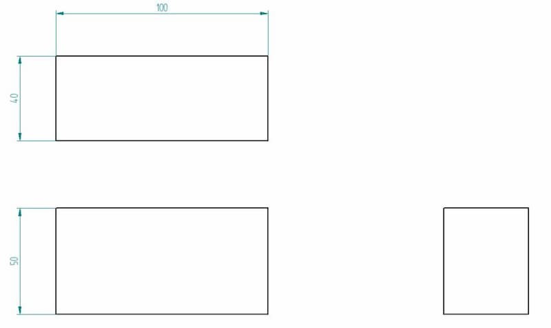
Nominal value is the basic dimension you usually give on a drawing. Without specifying the allowed tolerances, manufacturers will try to stay close to the value but there will be some sort of deviation as machine capabilities, setup, machinist competence, etc. all play a role.
Lower Deviation
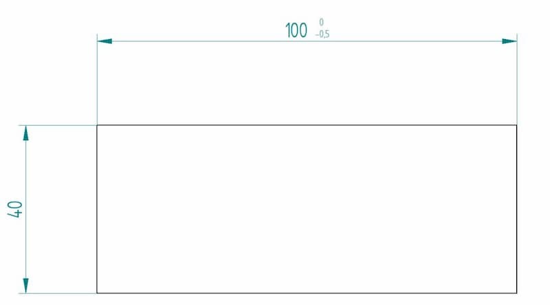
Adding a lower deviation tells the manufacturer how much smaller a certain measurement can be. This is noted using the "-" sign.When making the part on the drawing, a measurement between 99.5 and 100 mm is acceptable. Anything under or above is not withing the set limits.
Upper Deviation
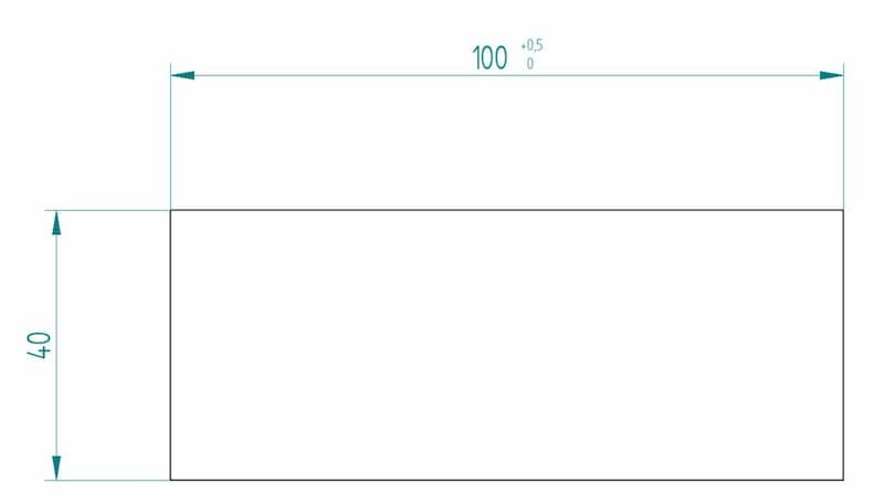
Upper deviation is the exact opposite of lower deviation. Adding it shows how much larger a measurement can be compared to the nominal value.
So the final measurement can be anywhere between 100 and 100.5 mm according to the tolerance limits on the drawing.
Bilateral Deviation
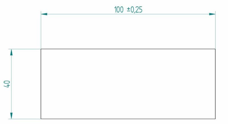
A third way to give a tolerance range is using bilateral deviations.
The drawing states that 99.75 as the minimum acceptable dimension and 100.25 mm as the maximum. Thus, the total “room for error” is still the same – 0.5 mm – but it can go either way from the nominal value by 0.25 mm.
A founded question here might be – is there any difference between a nominal value of 99.5 mm and an upper limit of +0.5 mm and a nominal value of 100 mm and a lower limit of -0.5 mm?
Now, if the manufacturer has made a box full of parts that fit into the range of 99.5 to 100 mm, they can send the parts out in both cases. So at this stage, there is essentially no difference.
However, the production partner will take the nominal value as the main reference point to strive for during the manufacturing phase. Thus, the 99.5 +0.5 mm box will likely contain more parts with a measurement of 99.6 mm and the 100 -0.5 mm box will come back with a larger portion of parts having a measurement of 99.9 mm.
General Tolerances
An engineering drawing may include general tolerances in the form of a table or just a little note somewhere on the drawing (e.g. "ISO 2768-m").
They can be applied to several conditions, including linear dimensions, angular dimensions, external radius, chamfer heights, etc. In Europe, the standard to follow is ISO 2768. ASME's Y14.5 is the US version of a similar standard but does not cover general tolerances. So, what does a note like ISO2768-m mean on a drawing?
That requires the manufacturer to follow the m (medium) tolerance class when making the parts. This applies to all dimensions unless stated otherwise on the drawing. Thus, a specific tolerance for a hole overrides the general tolerance requirements.Let's include the linear dimension table for better explanation:
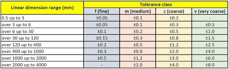
Here you can see that if a linear dimension falls into the 6 to 30 mm range, the permissible deviation is +/- 0.2 mm when looking at the m (medium) column. And for a dimension between 400 to 1000 mm, a tolerance of +/- 0.8 mm is allowed.
So 25.2 mm is acceptable for a 25 mm cut and so is 599.2 mm according to the standard for a 600 mm nominal value.
Fits
Shaft and hole matings come with a lot a different options and always require tolerances to obtain the right fit. But what is a fit in short? Limits and fits describe the allowance between the shaft and the hole. Allowance, in turn, is the maximum dimensional difference between the diameters of the two.
There are three types of shaft-hole engineering fits.
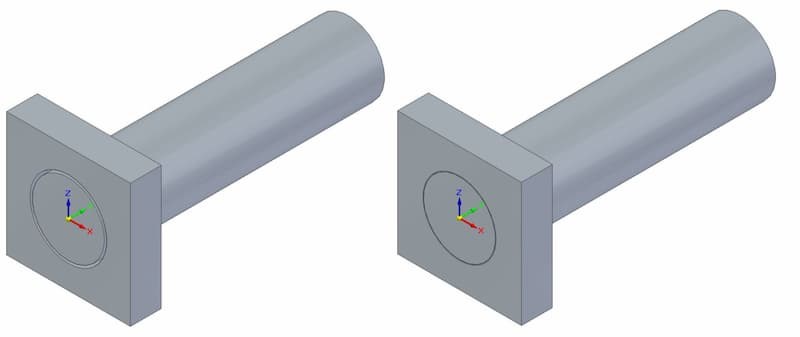
Clearance Fit
This type of fit requires a shaft diameter to be smaller than that of the hole. Meaning that there will always be a gap between the two.
If the engineering solution needs the two to be able to slide or rotate independently of each other, this is the way to go.So, in this case both the shaft and the hole have tolerances that will ensure no overlapping.
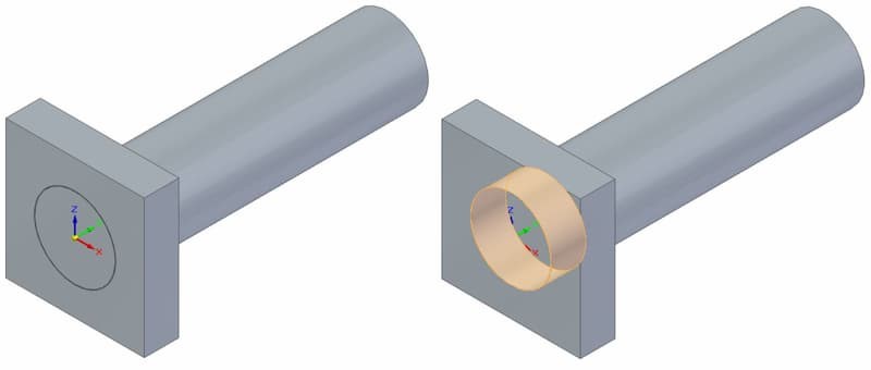
Transition Fit
This option means that the maximum shaft size is bigger than the minimum size of the hole. At the same time, the minimum shaft size is also smaller than the maximum size of the hole.
So it is neither a clearance fit, nor an interference one. Depending on the final measurements, the tolerances allow for both scenarios to happen while not going into the extremes.
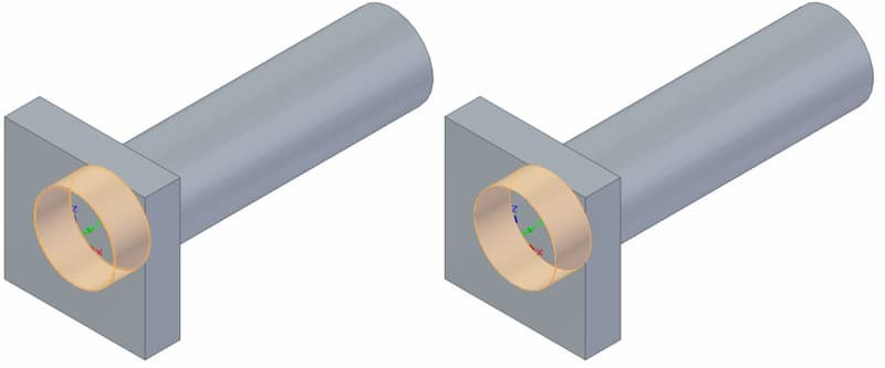
Interference Fit
Here, the shaft diameter size is always bigger than the hole. Even when the shaft is at its minimum diameter and the hole at its largest.
An interference fit ensures there is no movement between the two parts. Application of force is necessary during the physical fitting. Heating of the hole, freezing of the shaft and using a lubricant can all help to ease the process.
GD&T
Geometric dimensioning and tolerancing adds another side to engineering tolerance basics.
The system may seem a little daunting and intricate at first, but helps to convey requirements in a universally standardised way. GD&T defines the geometric tolerances for engineering products using in-part references.
For example, you can use it for defining the parallelism of two surfaces.
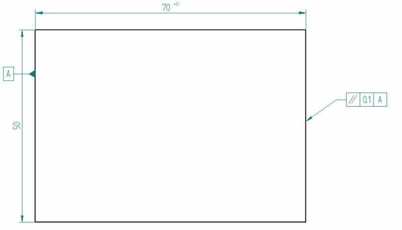
On the left, you can see the datum feature symbol. This assigns the left-hand surface as a reference.
The feature control frame pointing to the right side of the block has three elements – the parallelism symbol, the tolerance (distance between two parallel planes) and the datum reference.
So, what can we make of it all?
The left surface acts as a reference plane. As the machines will not be able to make both sides perfectly parallel but we require a certain limit, we gave it a parallelism tolerance.

Thus, the right side has to be parallel to the left side within a 0.1 mm tolerance, allowing for some deviation. The image above shows a possible outcome.
The right side is clearly tapered but within the limits (the green planes), therefore satisfying the set parallelism requirements.
Limits & Fits
In engineering, a fit refers to the clearance between two mating parts. The choice of an engineering fit determines whether the two parts can move relative to each other in case of a clearance fit, or act as a whole in case of a tight interference fit.
While limits and fits apply to all sorts of mating parts, their main use is for regulating the sizes of mating shafts and holes for best performance.
Both ISO and ANSI have standardised fits in three classes – clearance, transition and interference. Each class has a variety of options available for choosing the correct one for a specific application.
Tolerance Grade
With engineering fits, the tolerance will always be shown in analpha-numeric code. For example, a hole tolerance may be H7. The capital letter signifies that we are dealing with a hole. When indicating tolerance for a shaft, the letter will be lowercase.
The number shows the international tolerance grade (ISO 286). A tolerance class determines a range of values the final measurement can vary from the base measurement.
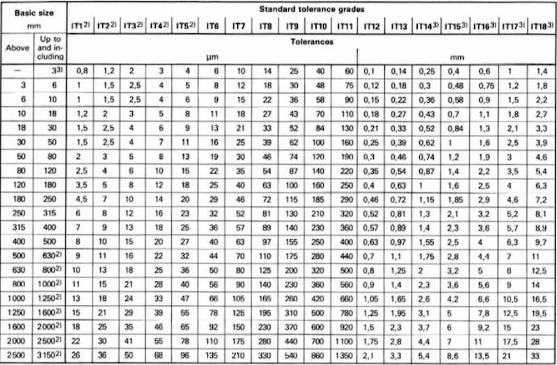
From the table, we can see that the tolerance grade applies to a range of basic sizes. So if we have a hole with a nominal size of 25 mm and a tolerance class of H7, we will fit into the 18…30 mm basic size group. Looking at the IT7 tolerance grade, the chart gives an allowed variance of 0.021 mm.
The letter signifies the start of the tolerance zone. For H7, the starting point is at exactly 25.000 mm. The maximum hole size is then 25.021 mm. For F7, the tolerance range is the same but the starting point is 25.020 mm, taking the last acceptable measurement to 25.041 mm.
A great way to find all the corresponding engineering tolerances to specific measurements is by using a limits & fits calculator.
Hole and Shaft Basis System
When choosing a system for a fit, you have 2 options – hole and shaft system. The system tells which part has a controlled measurement and which part is made based on the other.
In short, the hole-basis system uses a constant measurement for the hole and the diameter of the shaft is made accordingly to achieve the required fit.
And the shaft-based system works vice-versa.
Engineers tend to follow the hole system because of simplicity. As the hole size stays constant, the shaft's upper and lower deviation values determine the type of fit. Drilling does not allow for much precision, as the tooling comes in certain measurements. At the same time, CNC turning services are able to create shafts with exact measurements, so achieving the desired fit is just easier this way.
Limits & Fits

In engineering, we have to define the tolerances of parts to ensure a long lifespan and proper working of a machine. We can choose the fits according to the necessities and working conditions. The three main categories are:
- • Clearance fit
- • Transition fit
- • Interference fit
All these come with another subset of categories, each designed for different circumstances. Of course, we have to keep in mind that closer tolerances and more snug fits will result in higher costs because of higher demands on machining accuracy and the difficulty of assembly.
A clearance fit always leaves room between the two parts. A transition fit is somewhere in between clearance fits and interference fits and can end up either way but without leaving much room nor being too tight. A interference fit is tight and creating the fit requires considerable force and other techniques for easing the process.
Clearance Fits
With a clearance fit, the shaft is always smaller than the hole. This enables easy assembly and leaves room for sliding and rotational movement.
Max clearance – left; min clearance – right
When the shaft diameter is at its minimum and hole diameter at its maximum, we have a situation of maximum clearance. When the shaft diameter is at its max and hole diameter at its minimum, we have a situation of minimum clearance. Clearance fits come in 6 sub-categories. Starting from the loosest:
- • Loose running
- • Free running
- • Close running
- • Sliding
- • Close clearance
- • Locational clearance
Loose Running Fit
Fit with the largest clearance. Suitable for applications where accuracy is not of the utmost importance and contamination may be a problem.
Example uses in engineering:
Fits exposed to dust contamination, corrosion, thermal and mechanical deformations. Pivots, latches, etc...
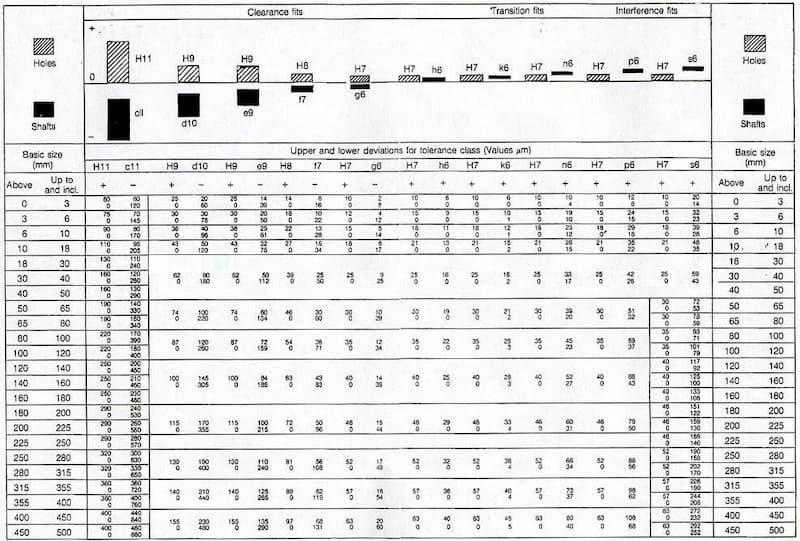
Example fits:
H11/c11, H11/a11, H11/d11 (all hole-basis), C11/h11, A11/h11, D11/h11 (all shaft-basis) Using a 25 mm diameter, a H11/c11 fit gives a minimum clearance of 0.11 mm and a maximum clearance of 0.37 mm. In this case, the shaft diameter can fall in between 24.76 and 24.89 mm while the minimum hole size is 25 mm and the max 25.13 mm.
Free Running Fit
Suitable where no special requirements apply to the accuracy of matching parts. Leaves room for movement in environments with heavy temperature fluctuations, high running speeds and heavy plain bearing pressures.
Example uses in engineering:
Applications where maintaining a film of oil lubrication is important. For example, shaft and plain bearing fits with little rotational movement.
Example fits:
H9/d9, H9/c9, H9/d10 (all hole-basis), D9/h9, D9/h8, D10/h9 (all shaft-basis) Using a 25 mm diameter, a H9/d9 fit gives a minimum clearance of 0.065 mm and a max clearance of 0.169 mm.
Close Running Fit
Close-running fits are a good choice for applications that require smaller clearances and moderate accuracy. Good for withstanding medium speeds and pressures.
Example uses in engineering:
Machine tools, sliding rods, machine tool spindles, etc.
Example fits:
H8/f8, H9/f8, H7/f7 (all hole-basis), F8/h6, F8/h7 (all shaft-basis) Using a 25 mm diameter, a H8/f7 fit gives a minimum clearance of 0.020 mm and a max clearance of 0.074 mm.
Sliding Fit
Leaves a small clearance for high accuracy while maintaining ease of assembly. Parts will turn and slide quite freely.
Example uses in engineering:
Guiding of shafts, sliding gears, slide valves, automobile assemblies, clutch discs, parts of machine tools, etc.
Example fits:
H7/g6, H8/g7 (all hole-basis), G7/h6 (shaft-basis) Using a 25 mm diameter, a H7/g6 fit gives a minimum clearance of 0.007 mm and a max clearance of 0.041 mm.
Locational Clearance Fit
Location clearance fits provide minimal clearance for high accuracy requirements. The assembly does not need any force and the mating parts can turn and slide freely with lubrication, helping with assembly by hand. Provides a snug fit for stationary parts.
Example uses in engineering:
Roller guides, guiding of shafts, etc.
Example fits:
H7/h6, H8/h7, H8/h9, H8/h8 (all hole-basis) Using a 25 mm diameter, a H7/h6 fit gives a minimum clearance of 0.000 mm and a max clearance of 0.034 mm.
Transition Fits
A transition fit encompasses two possibilities. The shaft may be a little bigger than the hole, requiring some force to create the fit. At the other end of the spectrum is a clearance fit with a little bit of room for movement.
Clearance – left; interference – right
Specifying a transition fit means that both outcomes are possible even inside a single batch.
Transition fits come in 2 forms – similar fit and fixed fit.
Similar Fit
Leaves a small clearance or creates a small interference. Assembly is possible using a rubber mallet.
Example uses:
Hubs, gears, pulleys, bearings, etc.
Example fits:
H7/k6 for hole-basis and K7/h6 for shaft-basis Using a 25 mm diameter, a H7/k6 fit gives a max clearance of 0.019 mm and a max interference of 0.015 mm.
Fixed Fit
Leaves a small clearance or creates a small interference. Assembly is possible using light force.
Example uses in engineering:
Driven bushes, armatures on shafts, etc.
Example fits:
H7/n6 for hole-basis and N7/h6 for shaft-basis Using a 25 mm diameter, a H7/n6 fit gives a max clearance of 0.006 mm and a max interference of 0.028 mm.
Interference Fits
Interference fits are also known as press fits or friction fits. These types of fits always have the same principle of having a larger shaft compared to the hole size.
Max interference – left; min interference – right
The assembly stage requires force, sometimes lubrication, heating of the hole and freezing of the shaft. These help to increase/decrease the hole and shaft sizes respectively to make for an easier process.
The interference helps to secure the relative positioning of the shaft and hub even during rotation, making this type of fit good for transmitting rotational speed and power.
Press Fit
Minimal interference. Assembly can be performed with cold pressing.
Example uses in engineering:
Hubs, bushings, bearings, etc.
Example fits:
H7/p6 for hole-basis, P7/h6 for shaft-basis Using a 25 mm diameter, a H7/p6 fit gives a min interference of 0.001 mm and a max interference of 0.035 mm.
Driving Fit
Needs higher assembly forces for cold pressing. Another way is by using hot pressing. This interference fit is more prominent than with a press fit.
Example uses in engineering:
Permanent mounting of gears, shafts, bushes, etc.
Example fits:
H7/s6 for hole-basis, S7/h6 for shaft-basis Using a 25 mm diameter, a H7/s6 fit gives a min interference of 0.014 mm and a max interference of 0.048 mm.
Forced Fit
High interference fit. Assembly requires heating the part with a hole and freezing of the shaft to force the mating parts together. Disassembly can result in broken parts.
Example uses in engineering:
Shafts, gears, etc.
Example fits:
H7/u6 for hole-basis, U7/h6 for shaft-basis Using a 25 mm diameter, a H7/u6 fit gives a min interference of 0.027 mm and a max interference of 0.061 mm.


 Pipe Extrusion Engineering Specialist